Automatic Slack Adjuster
S-ABA type
Start Position Pre-Set Running Clearance
In the start position the cut-out slot in the regulator is open. On the forward stroke the S-ABA rotates. The rotation of the S-ABA closes the cut-out as the regulator pinion rotates but the regulator worm shaft is held by the engaged conical clutch.
Excess Clearance Phase
If there is excess clearance or wear, the stroke will be longer and the S-ABA will rotate further. With the slot now closed, the one-way clutch in the regulator rotates in the slip direction. As the conical clutch is engaged the regulator worm shaft and clutch worm wheel do not rotate.
Elasticity Phase
When the brake linings touch the brake drum the S-ABA continues to rotate due to Elasticity in the brake. The increasing camshaft torque acts through the main worm wheel and main worm shaft, the coil spring is compressed and the conical clutch disengages.
Elasticity Phase
On the return stroke the S-ABA starts to rotate in the opposite direction. The conical clutch is still disengaged from the worm shaft so the regulator worm shaft and clutch worm wheel rotate freely. As the brake linings move away from the brake drum the camshaft torque drops, the coil spring de-compresses and the conical clutch re-engages.
Pre-Set Running Clearance Phase
The S-ABA continues to rotate. The regulator worm shaft is held by the re-engaged conical clutch but the regulator pinion rotates, opening the slot
Adjustment Phase
The S-ABA continues to rotate through the return stroke. The one-way clutch assembly is now rotating in the non-slip direction and drives the regulator worm shaft, rotating the clutch worm wheel. As the conical clutch is engaged the main worm shaft rotates and indexes the main worm wheel within the housing.
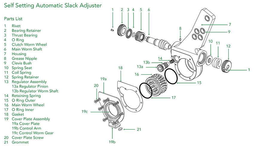
Installation instructions are common to ASA type and S-ABA type Automatic Slack Adjusters.
Do not use air wrenches or hammers. Their use will damage the product, prevent correct function and will void the warranty.

Make sure that the brake chamber push rod is fully released. A minimum pressure of 6 bar is required. Clean the camshaft spline.

Now,fit the wear indicator and return spring (if needed),and secure the slack adjuster on the camshaft.

Grease the camshaft spline. Fit the new slotted anchor bracket but do not tighten it.

Following the direction of the arrow on the slack adjuster body, rotate the control arm as far as possible. Do not hammer the control arm. Fix the anchor bracket by tightening the mounting bolts.

Fit the slack adjuster onto the camshaft. Pay attention to the arrow in the housing.

Rotate the hexagon nut clockwise until the brake lining touches the brake drum. Do not use an air wrench.

Match the hole in the slack adjuster with the holes in the clevis, by rotating the hexagon nut clockwise. Do not use an air wrench to do this.

Turn the hexagon nut at a 3/4 turn anti-clockwise to adjust the brake clearance. It should produce a loud noise. Do not use an air wrench.

Grease the clevis pin and then fit and secure it. It should be able to rotate freely.

Leave a ring spanner on the hexagon nut and apply the brakes 5 times. If the hexagon nut rotates clockwise, the slack adjuster is working correctly.
Popular items technical specification
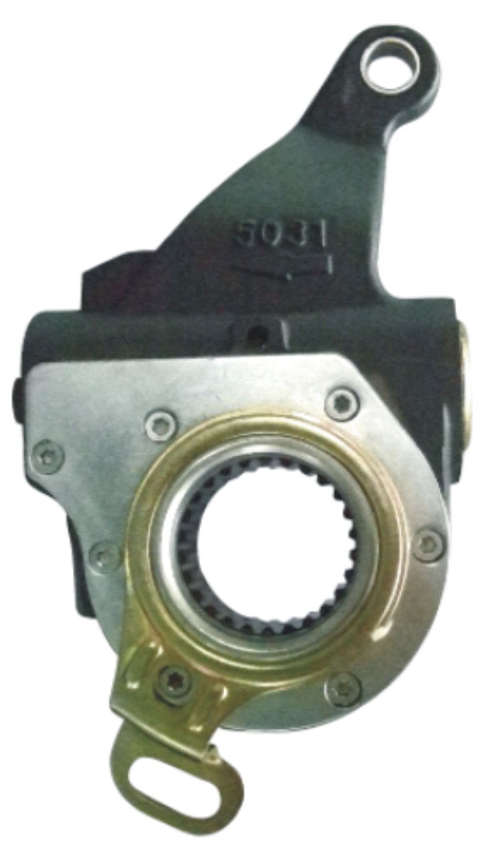
| JD no. | JD623314 |
|---|---|
| Part no. | 80014C |
| Casting | 5031 |
| No. of teeth | 26 |
| Control unit | 74527 |
| OE no. | 9454200438 |
| Application | MERCEDES-BENZ |
| Other side | 80030C |
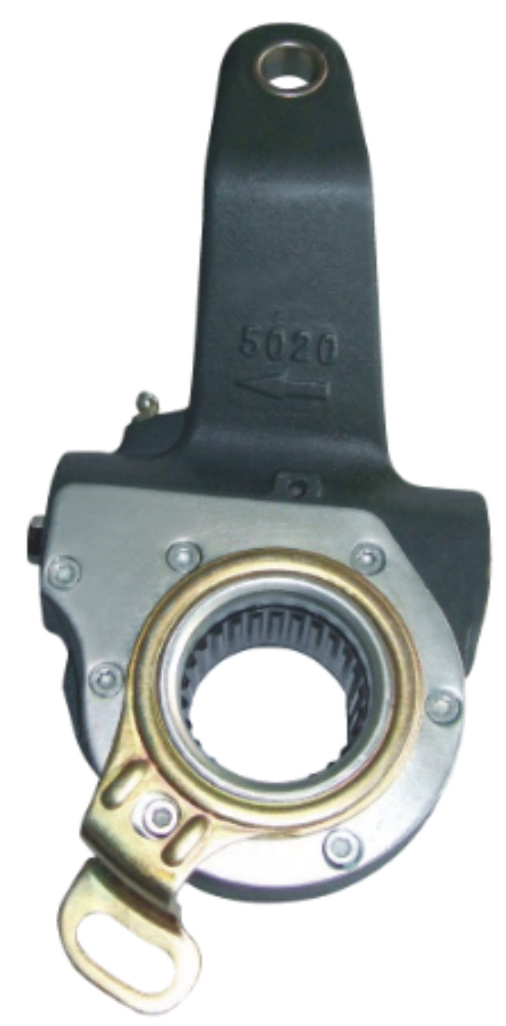
| JD no. | JD623480 |
|---|---|
| Part no. | 80180C |
| Casting | 5020 |
| No. of teeth | 26 |
| Control unit | 74537 |
| OE no. | 81506106261 |
| Application | MAN |
| Other side | 80181C |
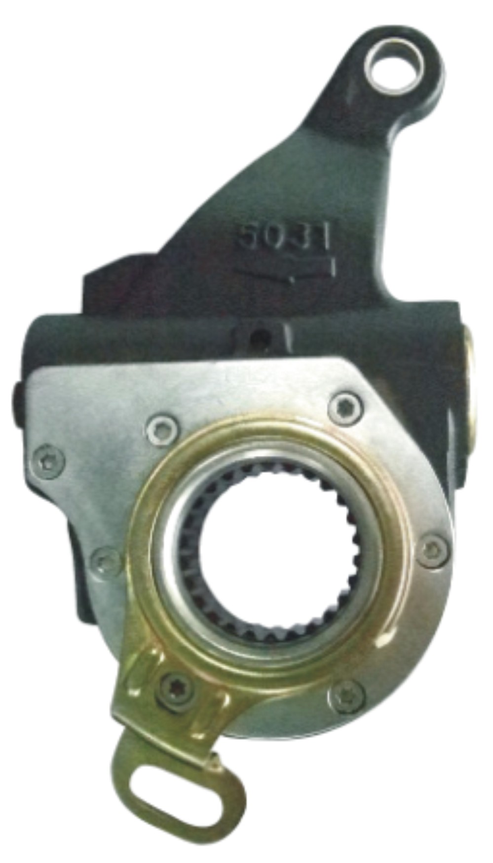
| JD no. | JD623483 |
|---|---|
| Part no. | 80183C |
| Casting | 5031 |
| No. of teeth | 26 |
| Control unit | 74535 |
| OE no. | 81506106266 |
| Application | MAN |
| Other side |
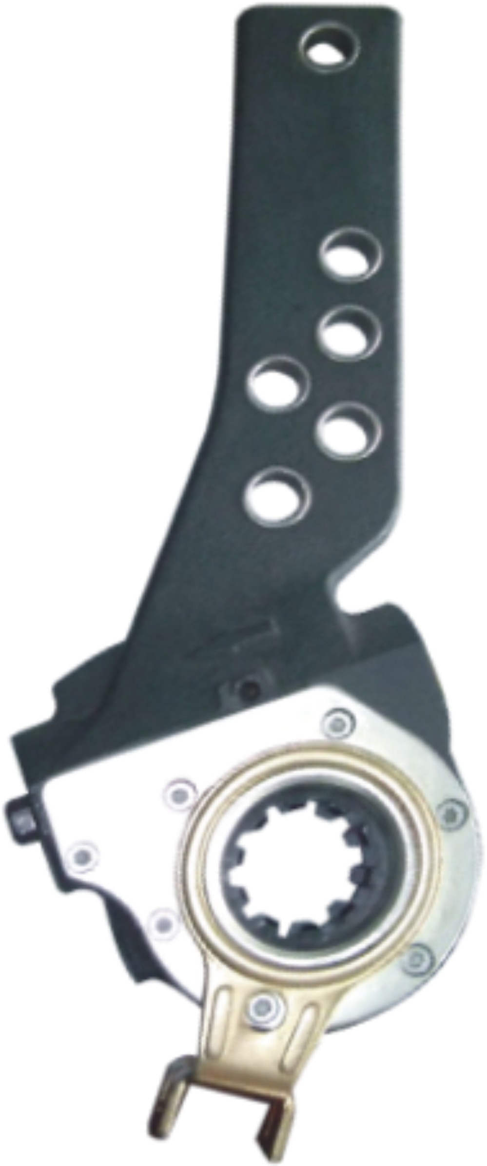
| JD no. | JD623322 |
|---|---|
| Part no | 80022D |
| Casting | 5027 |
| No. of teeth | 10 |
| Control unit | 74530 |
| OE no. | |
| Application | SAF |
| Other side |
Ask us for price and solutions today!
Your inquiry will be replied within 24 hours, and we respect your privacy.
HTML Forms powered by Wufoo.
